|
This is a speaker of the structure utilizing Fleming's left-hand rule of which most have probably heard once. This type of speaker includes those for TV and Audio, as well as earphones you use on commuter trains, and seems to this writer in this industry to account for more than 50% (probably further) of all the ordinary speakers used in the whole world.
Its excellent performance has made it possible to show such the diffusion.
On the other hand, its production requires gluing on most of the assembling processes, and is not easy to be automated due to its diverse sizes in spite of a large quantity production. Therefore, more than 90% of these speakers, except
for special specifications, are currently being produced in those countries where labor costs are inexpensive.
This kind of situation sometimes makes us feel uneasy about its future.....?
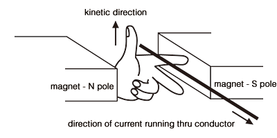
Fleming's Left-Hand Rule (John Ambrose Fleming 1849 - 1945):

- Forefinger shows a direction of magnetic flux running from north pole to
south pole of the magnet,
- With a conductor placed to cross the magnetic flux at right angles, get the
current running in the conductor in the direction indicated by the middle
finger,
- And then, a thumb shows a kinetic direction of the conductor.
Actual structure utilizing Fleming's left-hand rule:
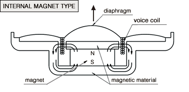
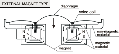
Two different kinds of structures are shown below, each of which has an internal and external type of magnetic circuit respectively.
Each type is composed of magnetic materials for a path of magnetic flux running from N pole to S pole of a magnet.
Voice coil is placed in a gap made in the path of magnetic flux (like a doublelayer wound coil as illustrated).
Referring to the above sectional view, when a current is fed into the dot direction, a move in the arrow direction extends to the voice coil in accordance with the above Fleming's left-hand rule. Then, the diaphragm, on which the voice coil is fixed, comes to move into the arrow direction.


Movement force of this structure is expressed by means of the following
equation:
| F=BáIáL |
F |
: Movement force (unit: N) |
| B |
: Magnetic flux density in a gap where voice coil is located (unit: Wb/m2) |
| I |
: Current running in voice coil (unit: A) |
| L |
: Length of voice coil crossing magnetic flux at
right angles (unit: m) |
With an instrument we had once managed to create to take a measurement of a diaphragm's compliance, we tried interestingly to verify whether the movement
was performing well to meet the above equation, and remember finding it affirmative with considerable accuracy. (while digressed from the main topic)
To raise the conversion efficiency in this structure, there are only three factors (B,
I, L) as you see the equation.
Raising the current would simply increase the movement force, but it does not necessarily mean increasing the conversion efficiency. Therefore, "B"
(magnetic flux density) and L (length of voice coil crossing magnetic flux at
right angles) are two factors to consider. Having "L" lengthened would raise
electric impedance, and substantially make a diaphragm heavier, which would
be undesirable for pursuing HiFi performance. Consequently, it would finally
force us to find a way to raise "B" value somehow.
Narrowing a gap where voice coil is located would be an effective way, because
it's said that magnetic flux is inversely proportional to the square of a distance.
Voice coil, however, needs to be set therein for this structure to exist, which
means that there is a limit to this idea. Lastly, the magnetic power would be
the one we could reply on.
Accordingly, it can be simply said that it would depend on a development
made by magnet manufacturers to improve the conversion efficiency.
This type, being of an excellence structure, still seems to have a slight weak
point for an issue of the conversion efficiency.
Enclosure of dynamic type of speaker used for the headphone:
Diaphragm is in general of a material having Hi compliance (low stiffness),
thanks to which it's possible to get "fo" (resonant frequency of speaker) set
lower. And, the enclosure's structure shall be so designed as to prevent
acoustic impedance from rising; otherwise it would bring the characteristic "fo"
to a higher frequency.
Ex.: Open-air type (whose structure allows a sound leakage from headphone's
enclosure) as you might have tried more than once is one typical example of the
structure.
In this Vol. 3, the contents have been limited to explanation of fundamental
structure of Dynamic Speaker, although there are various others to mention for
the topic of this "Structure". |
