This is to get into more detailed technical contents because a viewer with some technical knowledge seems to see the structure of 1-magnetic pole type balanced armature unit (explained in Technical Information Vol. 2) as a magnetic type of conventional structure.
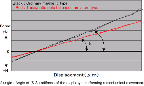
The following is a graph showing the measured values representing the relations of the forces inside an ordinary magnetic unit. (General readers, maybe, see this kind of curve of the actually measured values for the first time.)

Following is a graph showing the relation of the forces actually measured inside the 1-magnetic pole type balanced armature unit introduced in Technical Information Vol. 2 of this website.


 |
Relation of the forces inside the unit will be a little more described below :
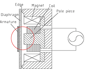
Measurements were done on the forces being generated at the red-circled portion in the left figure. |
S (Positive stiffness) :
Displacement and restoration of the diaphragm are shown. |
S' (Negative stiffness) :
Attractive force being generated at the diaphragm: Displacement point and attractive force are shown. |
S-S' (Positive stiffness - Negative stiffness) :
Diaphragm performs mechanical movement on this S-S' curve in a difference between its restoration force (S) and its opposite force (S'). |
Balancing point :
Point where the restoration force (S) and the attractive force (S') balance each other out. |
|

Following is a graph showing (S-S') comparisons with the above balancing points matched together.


Now, back to the main subject:
In this structure, it is the red-circled gap in the structure figure that decides the attractive force and the mechanical movement force through the electric signal.
That gap is made by three elements; magnet, pole piece, and edge. For another big element besides it, variations in attractive force of the magnet itself, and in stiffness of the diaphragm are also to be considered.
Under such the structural conditions, it is required to keep S`>S' for the stable movement.
* Diaphragm would be attacted to pole piece and magnetic surface in case S' force is bigger than S.
| ○ |
Unit assembled in such the restriction is an ordinary magnetic type. |
| ○ |
1-magnetic pole balanced armature type has the same fundamental restrictions, while big differences are to get less θ angle of (S-S'), which is not easily available in the conventional structure, as well as adjusting the power balance one by one unit to obtain a certain specific θ angle. |
This unit has same structure as before, but can be reborn by refinement as such a transducer as has high conversion factor and acoustic characteristic that the other acoustic transducers cannot follow.
Even a stereophonic earphone is also at the time of energy-saving nowadays! (Higher conversion factor means lower consumption of electric current at an apparatus used.)
There are so many people who use earphones these days.
Once you try one of our 1-magnetic pole balanced armature type earphones, I am sure, as an engineer in this field, that you would realize an obvious difference in the sound quality from those you have used so far.
 |
Reference data: |
 |
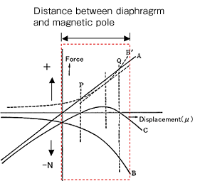
| Left figure shows the curves of the force mentioned in a piece of writing where ordinary electromagnetic transducers (magnetic types) are introduced. |
| Portion enclosed by a red dotted line indicates the graph of actual measurements shown above. |
| S : |
Graph A in the left figure |
| S' : |
Graph B in the left figure |
| S-S' : |
Graph C in the left figure |
|
| Designing done in the relation of forces like this graph would generate two of the balancing point (dotted lines of P and Q crossing the curve C), which would cause the movement to be very unstable. |
|
Views :
Relation of the forces is assumed to be drawn in view of the following two points of concept.
A : Attractive force of the magnet is inversely proportional to the square of the distance as generally said.
B : Stiffness curve shows a linear change.
As you see the graph measuring the relationship of forces, it is understood that the electromagnetic transducers (magnetic types) are not all in the force relationship that causes the balancing point to be unstable like the above figure.
|
